Start > Microcontroller based telescope driver III
Microcontroller based Telescope Driver III
This is my newest system which is still under development.
In this design I use Infineon TCA3727 stepper ICs like I did in the first modular scope controller.
But here these ICs are used only because of their current limiting capability.
Microstepping is done via PWM controlled directly by the CPU.
Therefor the AVR mega128 processor has two independent 16 bit timers with having two
PWM channels each (for two coils per motor).
For microstepping both timers run with constant frequency generating indepentent interrupts.
In the interrupt routine the PWM values for the next cycle and the current phases (+/-) are set.
The PWM timing is done entirely in hardware.
The interrupt routines set the PWM parameters for the next cycle in advance so even if both interrups
occur at the same time there will be enough time for the CPU to set all control registers in time.
When a motor ramps up to higher speed the interrupt routine automatically
switches into halfstepping mode. Then the PWM timer frequency is adjusted to one halfsteps duration
and 100% PWM on time (or 0% according to the stepping sequence) is used.
When the speed further increases the timer period becomes shorter.
So perfect halfstepping intervals are possible for both motors running at different speeds.
The mega128 processor is the only one having these two independent PWM timers.
It has 64 pins and is available only as 'Thin Plastic Quad Flat Package' (TQFP) with 0.8mm (0.0315")
pitch for surface mounting.
So I couldn't use a prototype board for this scope controller.
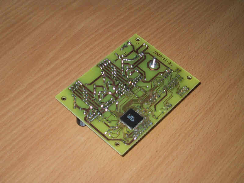
To keep it as simple as possible I designed a single layer PCB and soldered the CPU on the back.
Some wire bridges (17) still have to be on the top side but I avoided making a two layer PCB.
The handbox has eight buttons and a 2x8 character display (HD44780 compatible).
I plan to control all functions from this handbox similar to other commercially available scope controllers.
A menu will be programmed. Then more and more calculations will be coded in the AVR.
At the end the PC which is still connected via RS232 will be obsolete.
Later I will replace the ribbon cable by a more robust shielded cable.
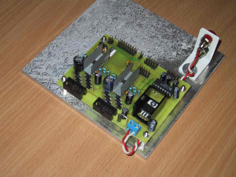
Controller board
The main board of the controller is small, measuring only 100x75 mm (4" x 3").
For the TCA3727 stepper controllers a large copper area is recommended for cooling.
Instead I built simple heat sinks from thin steel sheet (copper will work too) and soldered
them directly at the IC's ground pins. The motor current is limited to 500 mA per coil.
Then the maximum power dissipation will be 2.5 Watts per motor at 24V.
Controller board back side with surface mounted CPU
Some data of the Atmel AVR mega128
64 KWords Program Memory (self programmable flash)
4 KBytes RAM
4 KBytes EEPROM
16 MHz speed, 1-2 cycles per instruction
32 registers (8 bit, three pairs usable as 16 bit pointers)
Current development status (2004-02-22)
Floating Point Poutines
IEEE 64 bit floating point routines for ADD,SUB,MUL,DIV,SQRT,SIN,COS,ATAN written and tested.
Added correct handling of zero and overflow results
Next: ATAN2 function, More comments in the code, test with difficult special cases
Coordinate Transformations
Two star alignment routine works, finds Z3 automatically
Exact (non iterative) transformation of mount coordinates (apparent <-> true) incl. Z1, Z2
Tracking and Goto works
Successful indoor tests with mount simulator and laserpointer
First successful test with telescope 2002-02-20
User Interface
LCD shows current sky position when the scope is moving.
Menu tree for access of controller functions
Next: Display some messages (feedback after actions, warnings, errors)
Object Database and Pointing
Directory of memory 'files' containing object data:
64 alignment stars, all NGC and IC objects
Input of any target RA/DEC position on the handbox via left/right keys
Next: Support for user defined lists in EEPROM
Hardware
Added serial EEPROM in the PCB layout
Added Fuse and protection diodes in the PCB
Next: Build new prototype based on the layout